

Score: 4.5 (votes: 2)
Reviews: 1
On the 1986-92 RX-7s Mazda introduced the Dynamic Tuned Suspension System (DTSS). DTSS allows each wheel to steer by itself based on how many Gs of cornering force the outside wheel is generating. In stock form, cornering forces operating on the rear upright cause up to approximately 1 degree of toe-in on the outside wheel in a turn. This characteristic tends to compensate for driver input or road variations that might cause a vehicle to go out of control. However, this same characteristic also interferes with the feedback that a sensitive driver needs to operate his car near the limit of adhesion and generally reduces the ultimate cornering force.
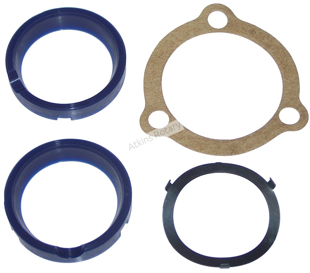
Toe Eliminator - a rigid joint that replaces the stock rubber joint - provides a perceptible improvement in feedback to the driver. There is no longer a need to modulate inputs based on the constantly fluctuating elastic joint output. The kit consists of two (2) rigid plastic sleeves and two (2) steel bushings which should be installed with the aid of a hydraulic press or a large vise. No re-alignment is necessary after installation.
Instructions Below
Instructions:
1. Raise the rear of the RX-7 chassis and support with jack-stands. DO NOT WORK UNDER A CHASSIS SUPPORTED ONLY BY A FLOOR JACK.
2. Remove both rear wheels.
3. Remove the large locknut and washer from the outboard end of each rear axle. This can be accomplished easily by either using the appropriate impact wrench OR having an assistant depress the brake pedal firmly while you loosen each nut using a wrench with a handle long enough to provide adequate torque. Mark the nuts so that they can be later identified as left-hand and right-hand nuts.
4. Being extremely careful to not allow the brake calipers to hang by their brake line hoses, unbolt the brake calipers from the aluminum bearing carriers. It is best to tie the calipers up and away from the work at hand, using a length of wire or rope.
5. Remove the three bolts that attach each aluminum bearing carrier to the rear suspension. Now remove the bearing carriers from the chassis. Do not attempt to remove the rear-steering bushing bolt at this time.
6. The brake rotors must now be removed from the stub axle flanges as follows: Remove the (2) screws that retain each rotor to the stub axle flange and pull the rotor off of the assembly. If the rotor will not separate from this assembly, use the (2) mounting screws you set aside earlier during this step and thread these screws into the threaded holes located on the back-side of the stub axle flanges. By evenly threading these screws from the back- side you will be able to push the rotor from the flange. DO NOT USE A HAMMER AT ANY POINT DURING THIS STEP—YOU RISK COSTLY DAMAGE TO THE ROTOR AND/OR WHEEL BEARING.
7. Once you have removed the (4) bolts which retain each dust shield to its bearing carrier you are now able to remove the rear-steering bushing bolts.
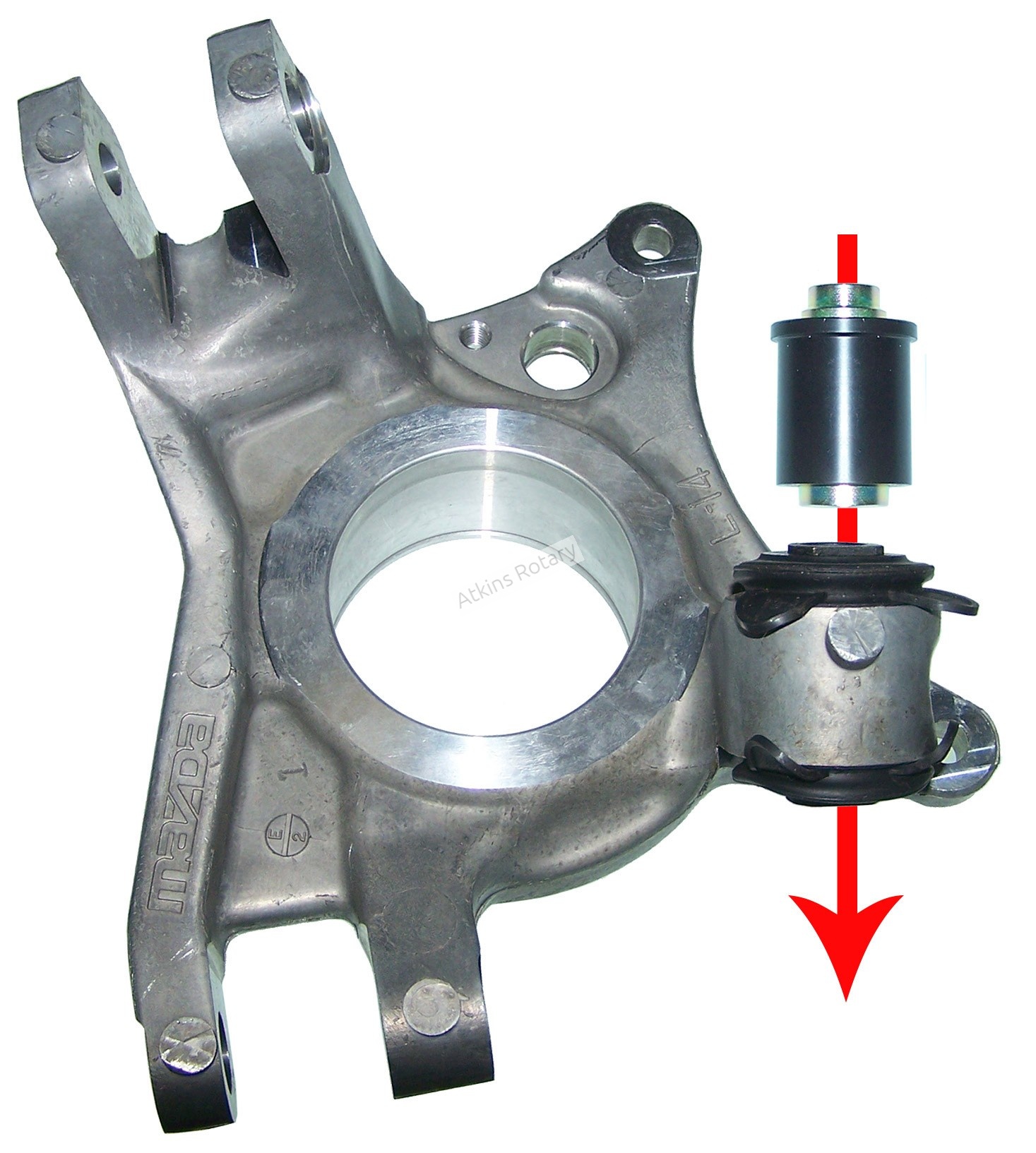
8. Having removed the rear-steering bushing bolts from the carriers you need to now press out the rear-steering bushings from each bearing carrier using a hydraulic press. THE BEARING CARRIERS MUST BE SUPPORTED DURING THIS STEP.
9. Clean the bushing bores from which you pressed out the rear-steering bushings. Lightly lubricate these bores using grease or vaseline.
10. Dis-assemble the Rear Suspension Upright Toe Eliminators by simply removing the steel inner bushings from the black Delrin outer bushings. Apply a light coating of grease or vaseline to both the steel inner bushings and the black Del-rin outer bushings and reassemble. IT IS EXTREMELY IMPORTANT THAT THESE BE REASSEMBLED AS FOLLOWS: When the steel bushing is re-inserted into the black Delrin bushing, the machined step found on one end only of the steel bushing must be protruding from the end of the black Delrin bushing that has the machined lip (flange).
11. (Figure 1) Orient the parts in the correct position as shown below) by holding each bearing carrier in its upright posi-tion, as it would mount on the chassis, and inserting the assembled steel/Delrin bushing assembly into the bearing carrier from the top of the bearing carrier. Press the steel/Delrin bushing assembly into the bushing bore until the lip (or flange) contacts the aluminum. DO NOT PRESS BEYOND THIS CONTACT POINT: YOU RISK DAMAGE TO THE DELRIN BUSHING.
12. Re-install the aluminum bearing carriers by reversing steps (2) through (7). NOTE the following: First, re-install the lower arm of the bearing carrier. Next insert the bolt at the Delrin bushing position and start its threads. Lastly install the bolt in the upper arm of the bearing carrier, being certain to re-install the thin plastic disc between the aluminum upper arm and the suspension AT THE REAR OF THIS JOINT on each side. Install the large nut which was removed from the left rear axle onto the right rear axle. the remaining nut is installed onto the left rear axle. This reversing of nuts will allow you to stake the lock nuts in a new location.
Tightening Torque Specifications:
• Delrin Bushing Bolt 100 FT-LBS
• Brake Caliper Bolts 38 FT-LBS
• Rear Axle Nut 200 FT-LBS*
• Top & Bottom Bolts In Bearing Carrier 55 FT-LBS
* DO NOT FAIL TO STAKE THE REAR AXLE NUTS INTO THE AXLE SLOTS.